
Those who have read the previous posts about my cargo moped, know that the motor is prone to overheating. This is probably somewhat caused by the changed gear ratio for increased speed. But I also know others have suffered from overheating even with stock gears when using the moped for longer periods.
This, of course, calls for a motor upgrade! But what to choose? As always, it’s fun to try to keep the cost down so anything used is interesting.
Today brushless AC motors are both common and rather cheap. A simple drop-in replacement can be found from Chinese suppliers, but judging from various Youtube videos of similar conversions doesn’t impress me. Then here are the hub motors available from Asia. Some of the companies seems pretty serious and these motors/rear wheels are used in commercial products. Unfortunately, the price was a tad high and most of these motors are built for high voltages (70-90 VDC). This didn’t fit my intended 48 V battery upgrade…
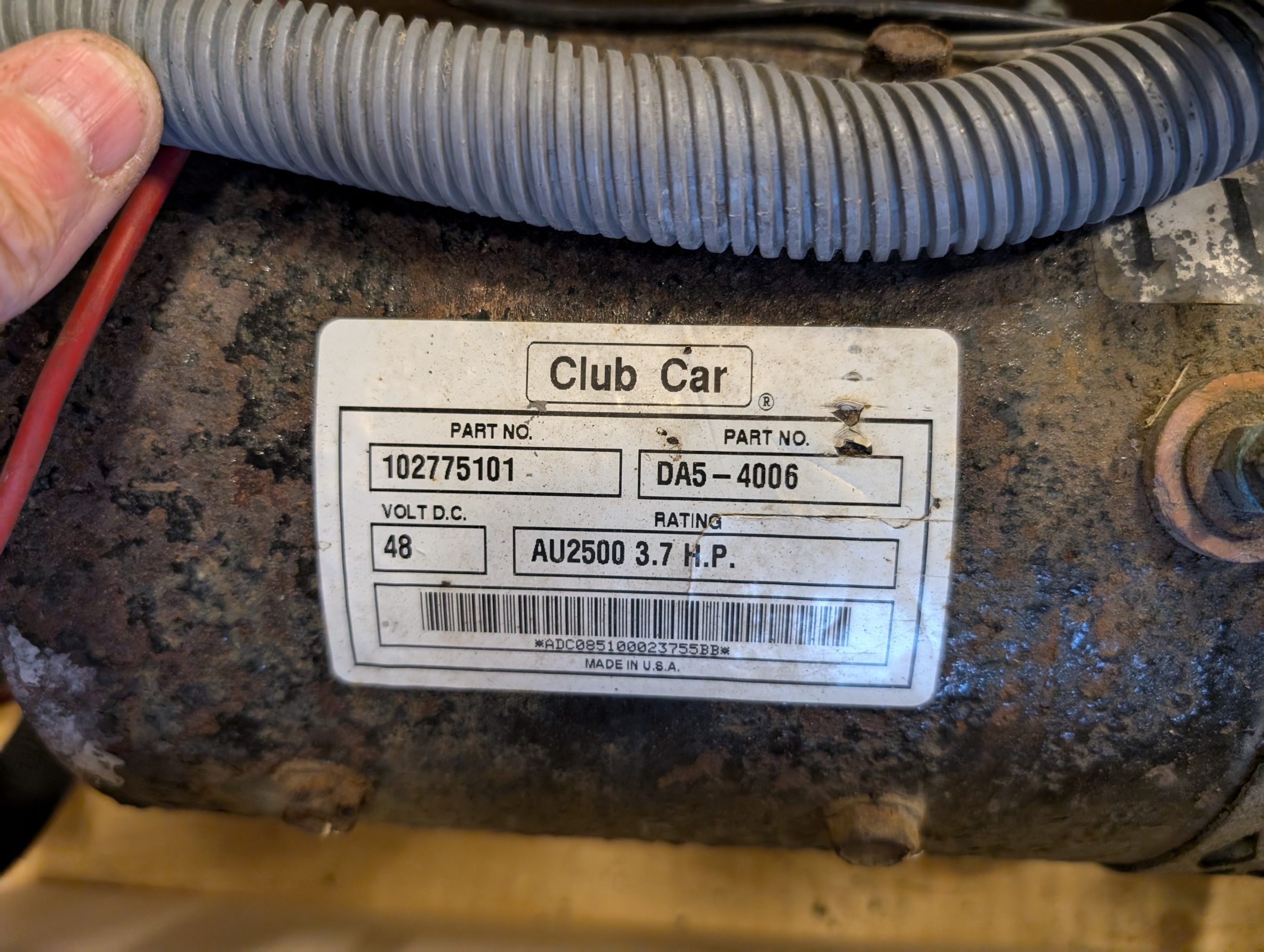
Then a golf cart motor appeared on Facebook Marketplace. This was not only the motor but complete electronics and wire harness from a stripped car, stripped from a 48 V Club Car. Deal!
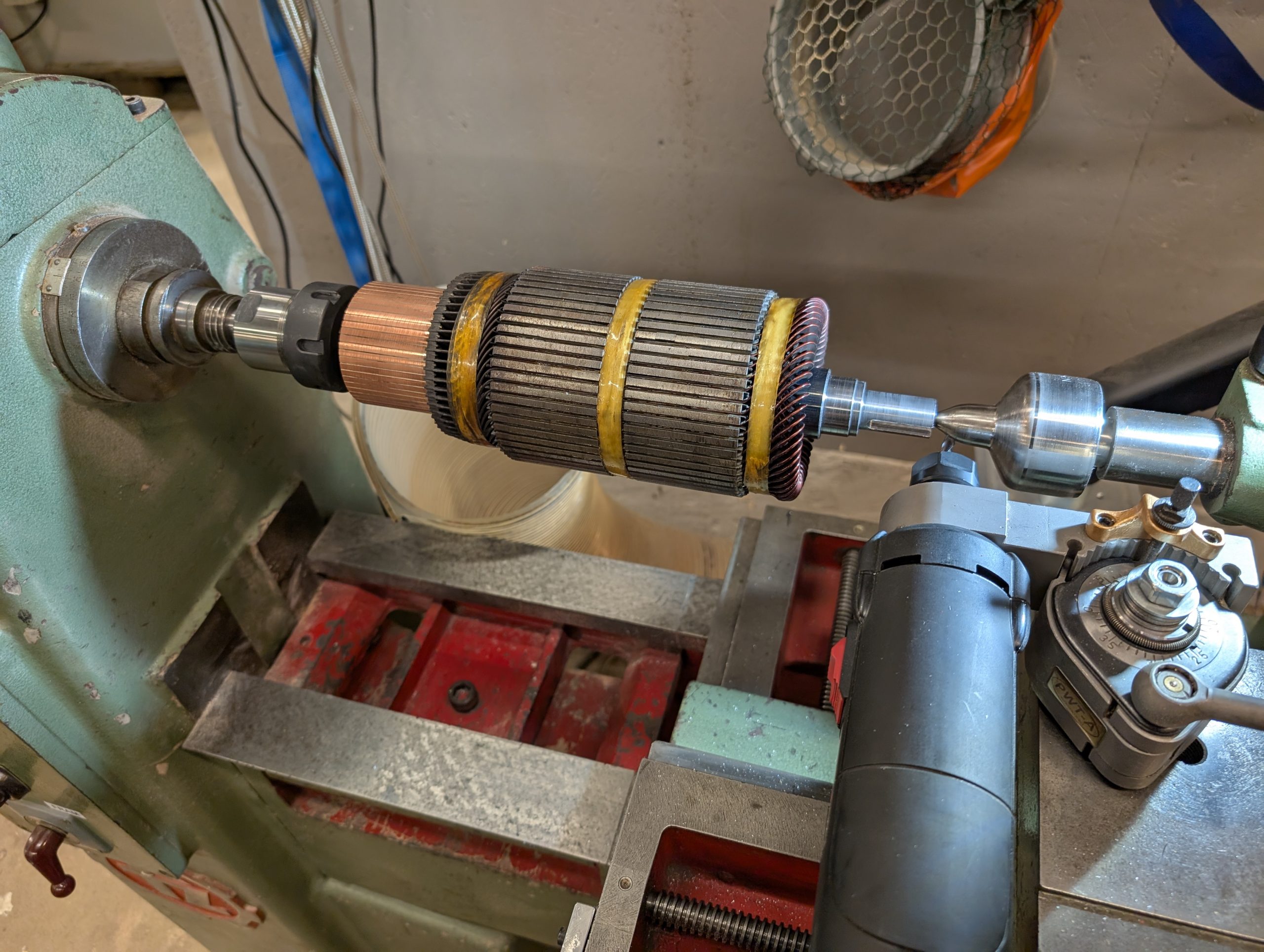
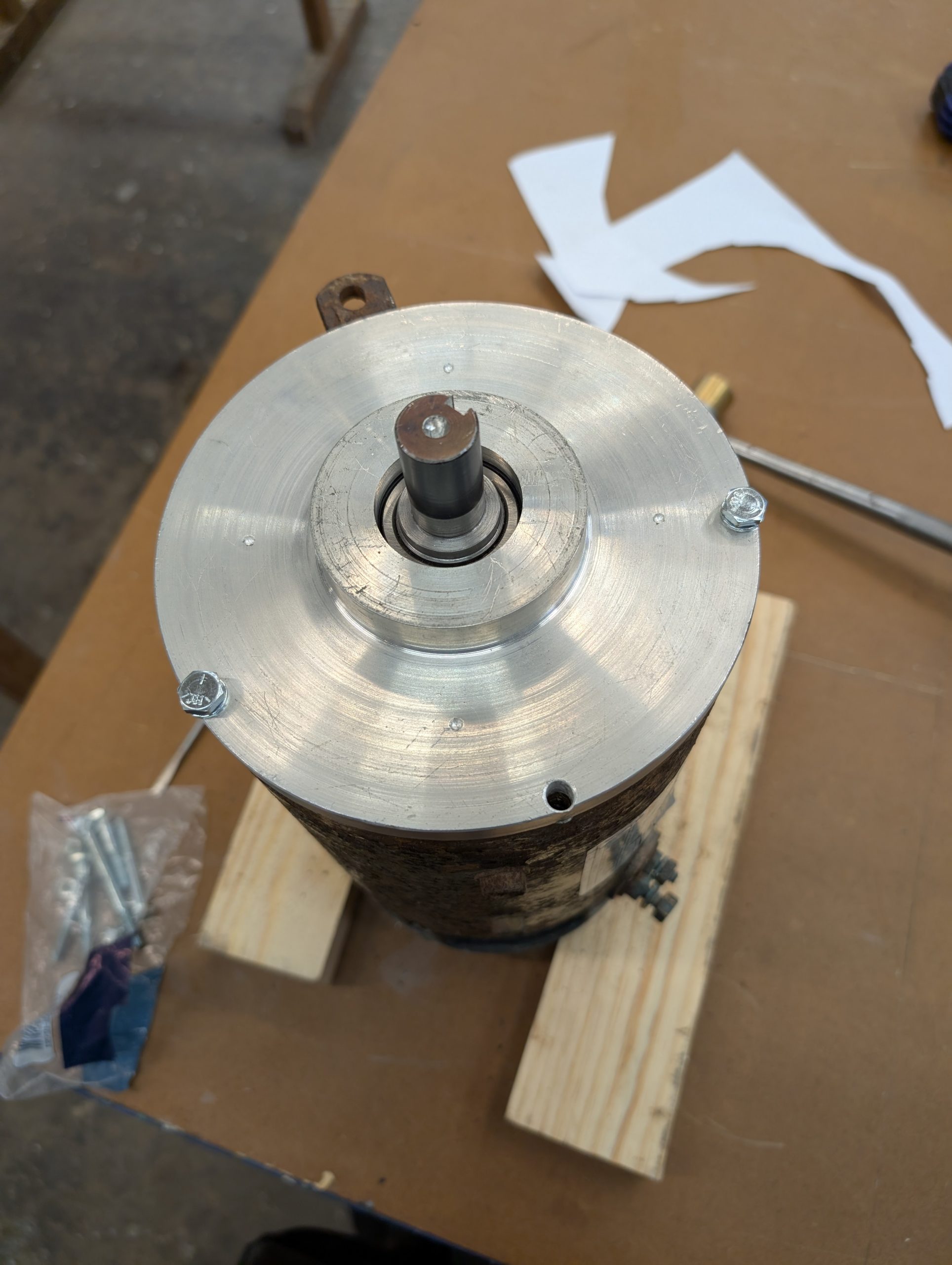
Before I bought the kit, my investigations showed that common golf cart motors only have end plates and bearings on one side. The other side is supposed to be docked to the gear box using a splined shaft. It was obvious a new end plate with bearings was needed. Also, the motor shaft was too short with only a bushing with an odd spline. I also made sure the motor physically could fit where the stock motor is mounted. It was tight but possible.
I found about one (1!) documented project where someone had built something similar so not much of inspiration. As long as the shaft could be extended, the plate and bearing could be solved. The existing bushing was hardened and shrunk onto the shaft. Removing it was a pain, leaving me with a bare shaft. What to do with that?
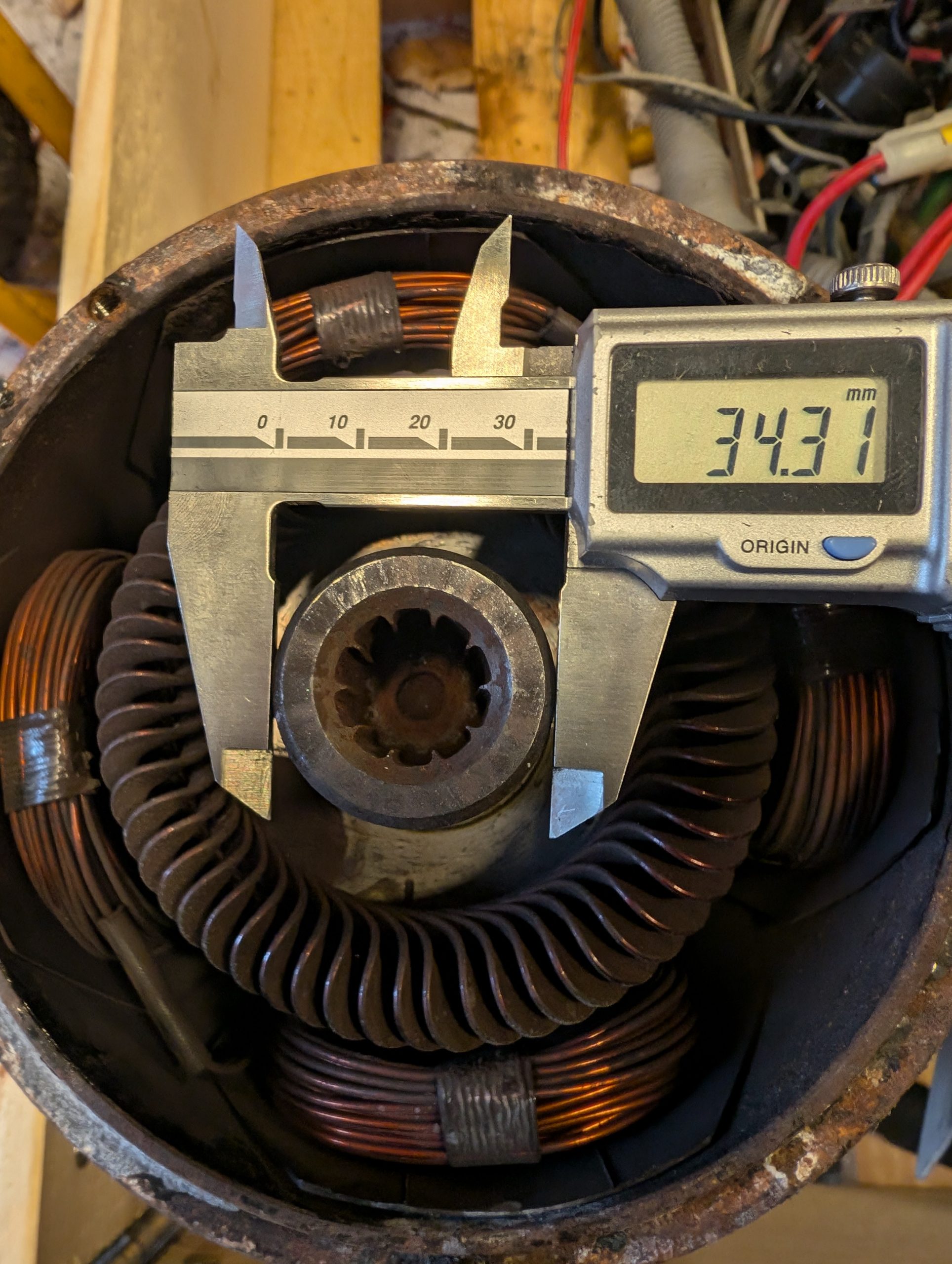
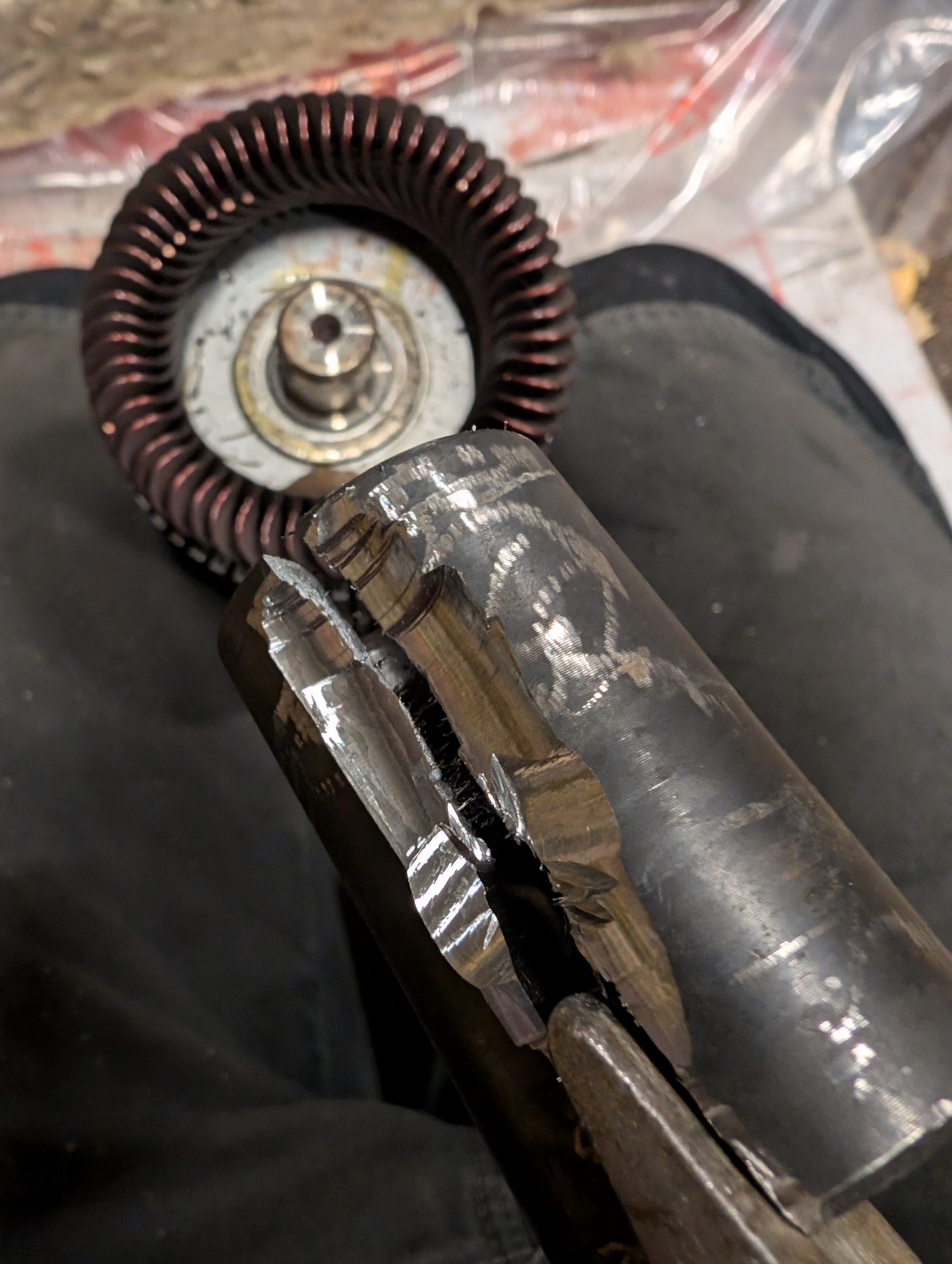
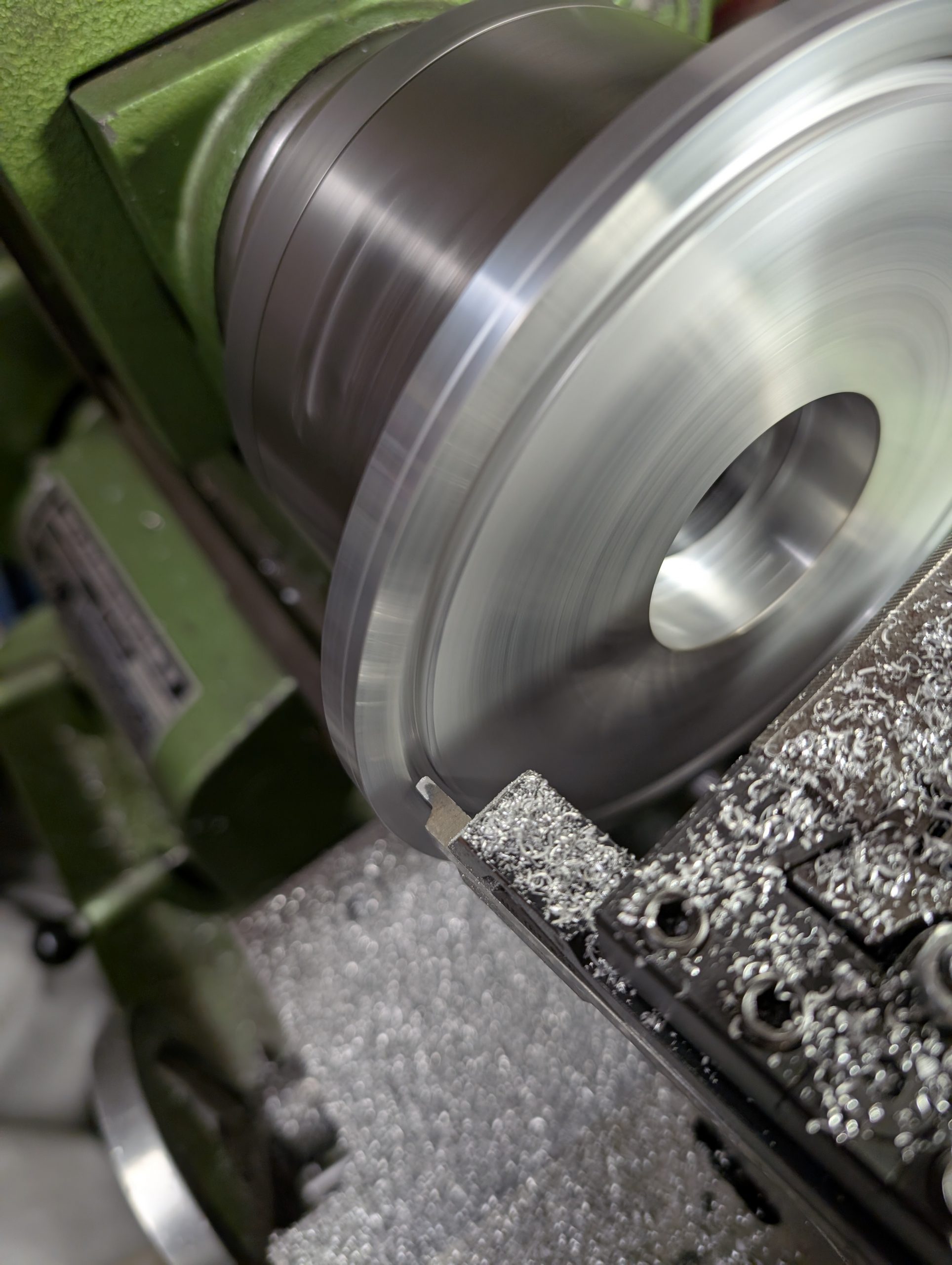
Why not try to do something similar. That is, turn a new shaft that could be shrunk onto the shaft. I have never done anything like that and I only got some indications on what tolerances was needed to get a tight fit.
First, the bushing part of the shaft was turned within specs. Idea was to turn the rest by mounting the complete motor rotor and new shaft in the lathe. I then prepared by borrowing a hydraulic press at a neighbor to be prepared for any problems during the mounting. But first I heated the new bushing and tried to cool down the shaft. At that point, the press wasn’t needed and the bushing just slid on and then shrunk and gave a tight fit. Question was if that was enough.
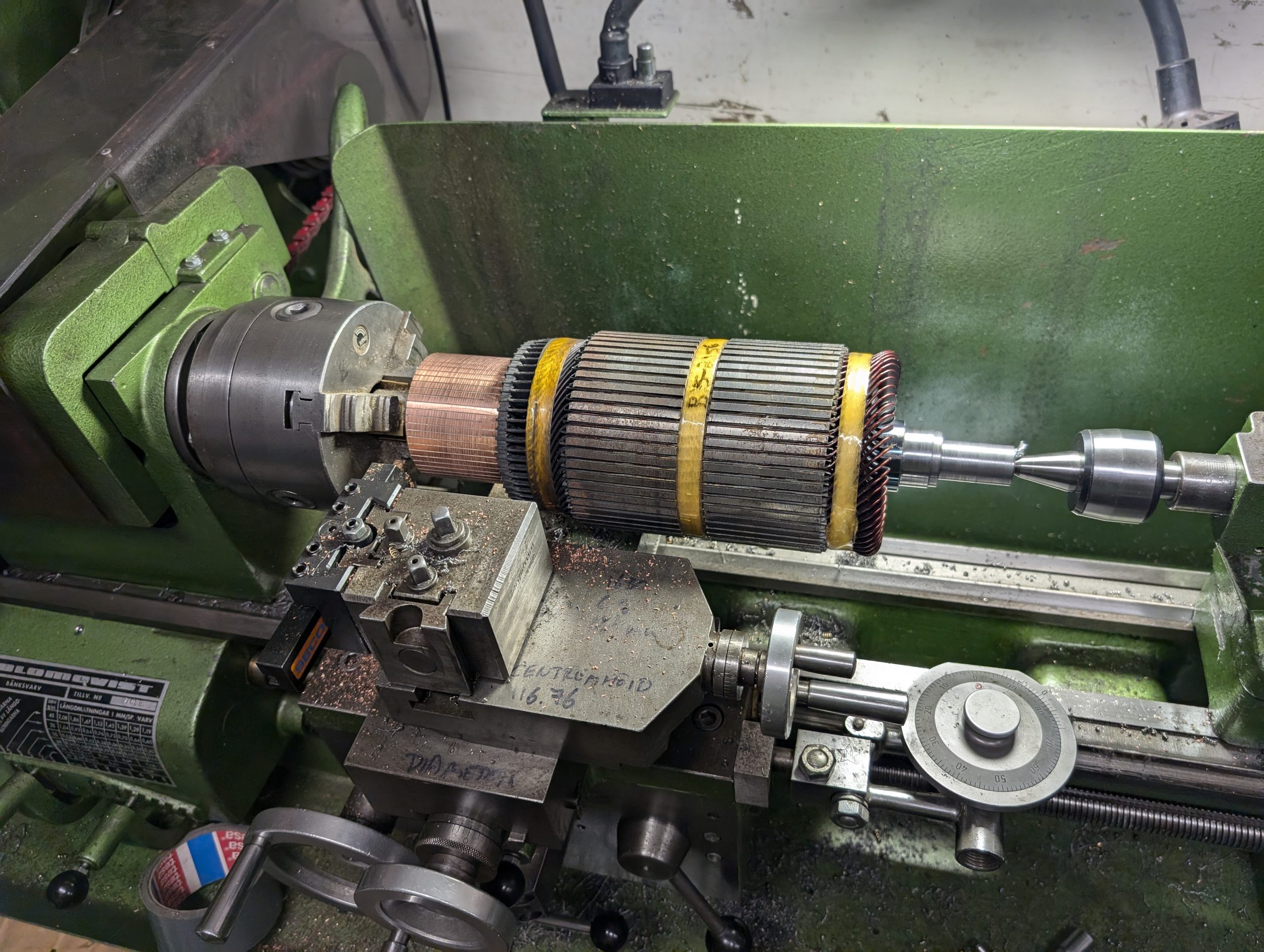
Everything went into the lathe. Cursing not having a steady for setting everything up, I did my best to get a center hole in the new shaft. It went better than expected and the shaft was turned to a diameter of 20 mm.
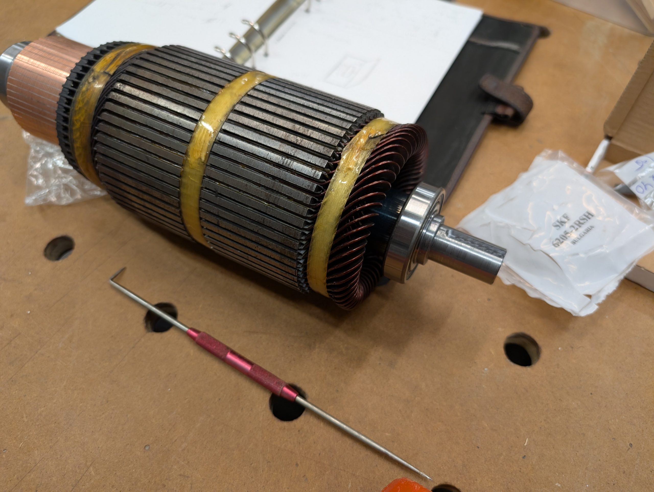
To be able to secure a pulley on the shaft, a key slot was needed. A 6 mm HM router bit was sacrificed for this.
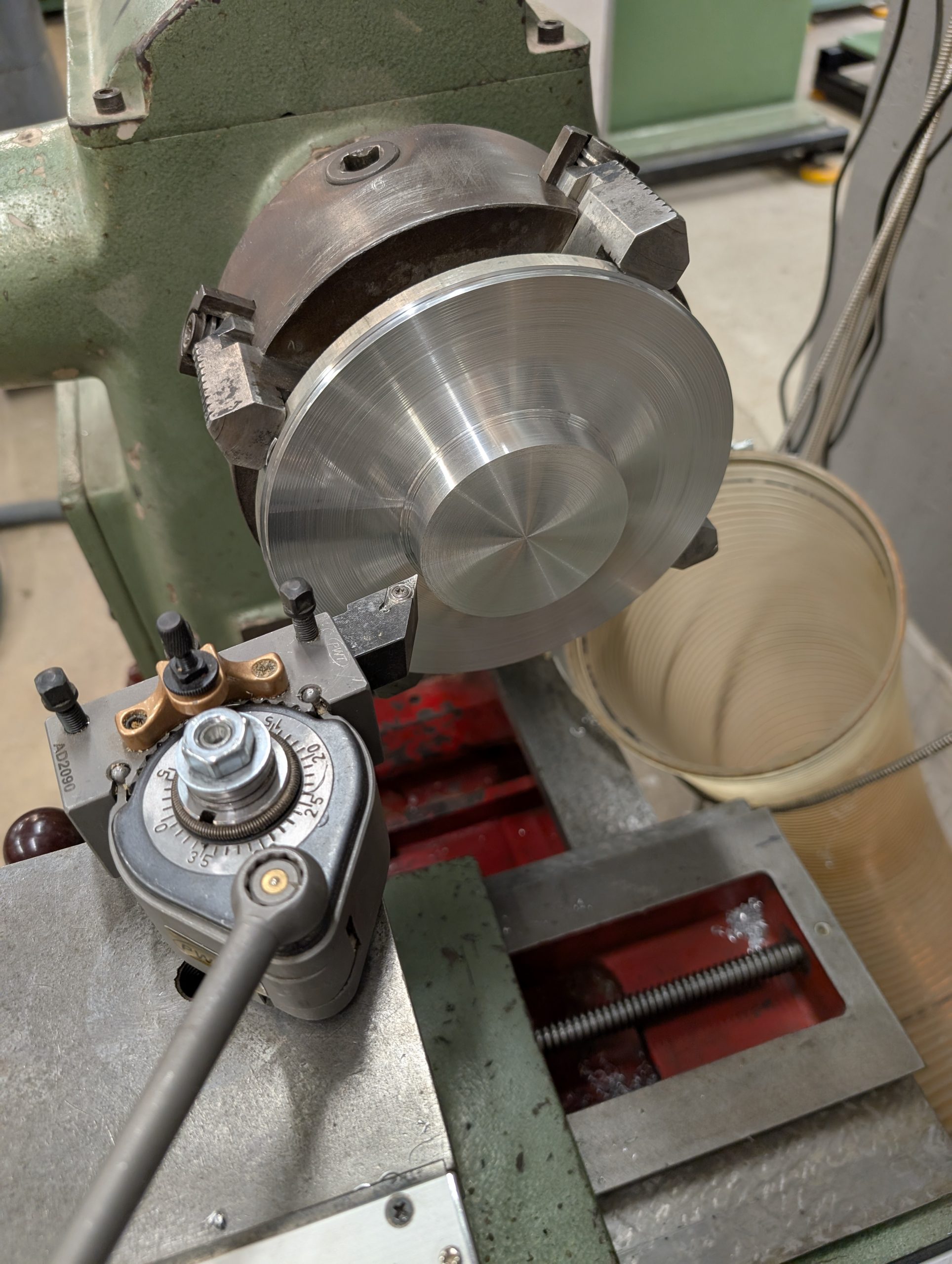
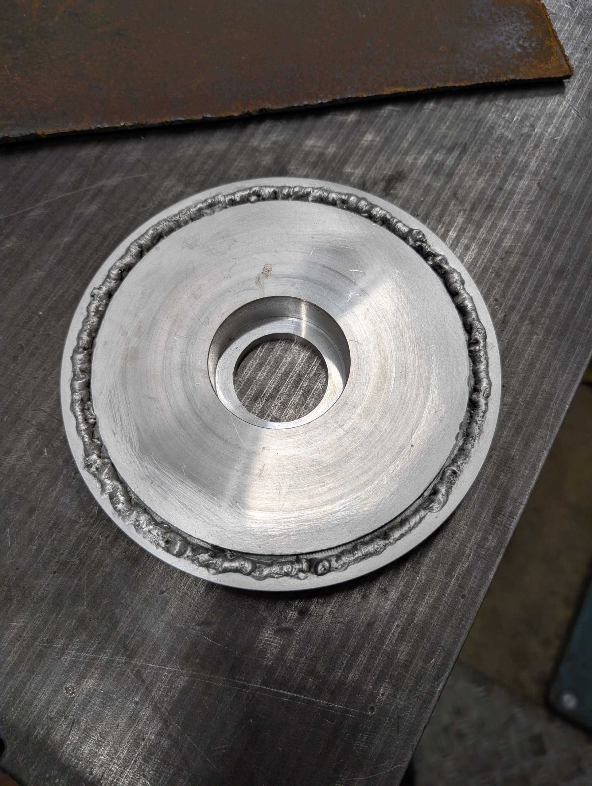
The new end plate was made of aluminum for easy turning and reduced weight. Unfortunately I messed up the measurements resulting in a loose fit to the motor. I had to fix that by adding back some material to the plate. This was my first attempt to weld aluminum using a crappy TIG welder. Well, it worked good enough.
The motor is a beast. The weight must be 25+ and it is much larger than the stock motor. It is rated at 3.7 hp (2.8 kW) but I suspect the peak power is much higher. One indication of that was that the original controller for it is rated for 500 A. 500 x 48 = 24 kW! Anyhow, my batteries are only speced for 1C (105 A) continuous discharge so things needs to be current limited.
At this point I had no idea of what the RPM of the motor was. Crucial information to calculate the gear ratio for the drive train. The only way I could get any kind of idea was a motor test run. Unfortunately that required a powerful 48 VDC source (battery upgrade still in the future). Got a cheap 48 V PSU from Amazon and concluded the max speed was about 2500 RPM. I then realized the “AU2500” marking in the “Rating” field on the label on the motor may indicate this :)
The next part will continue upgrades of the drive train, the electronics box and the batteries.