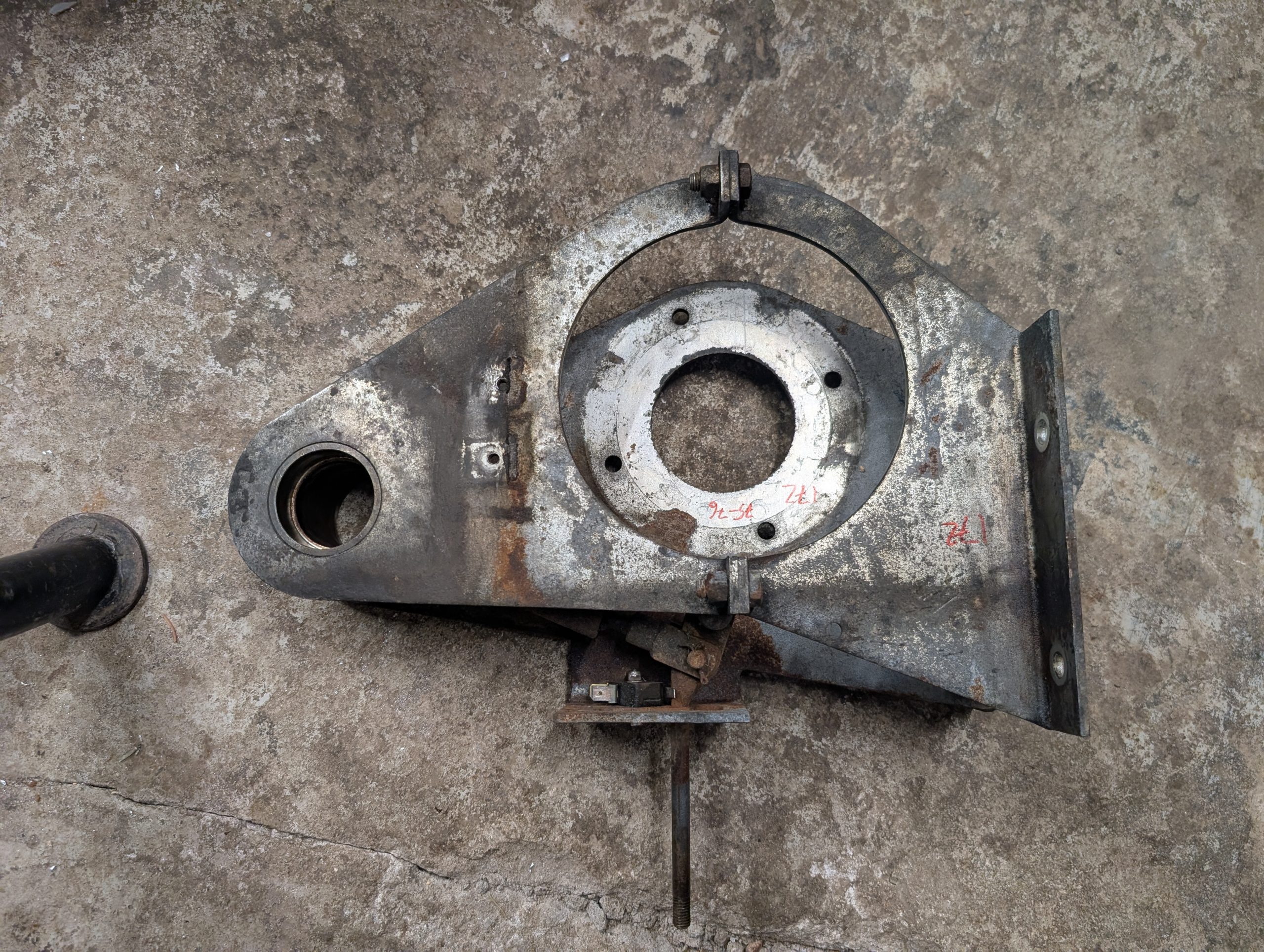
The most obvious part of the motor upgrade is the actual motor swap. As mentioned, my measurements indicated the new motor would fit at the same place as the original. That is, mounting the motor with the shaft at the same center as before, it would not hit any part of the frame. Of course, the actual mount needed to be modified but that was no big deal.
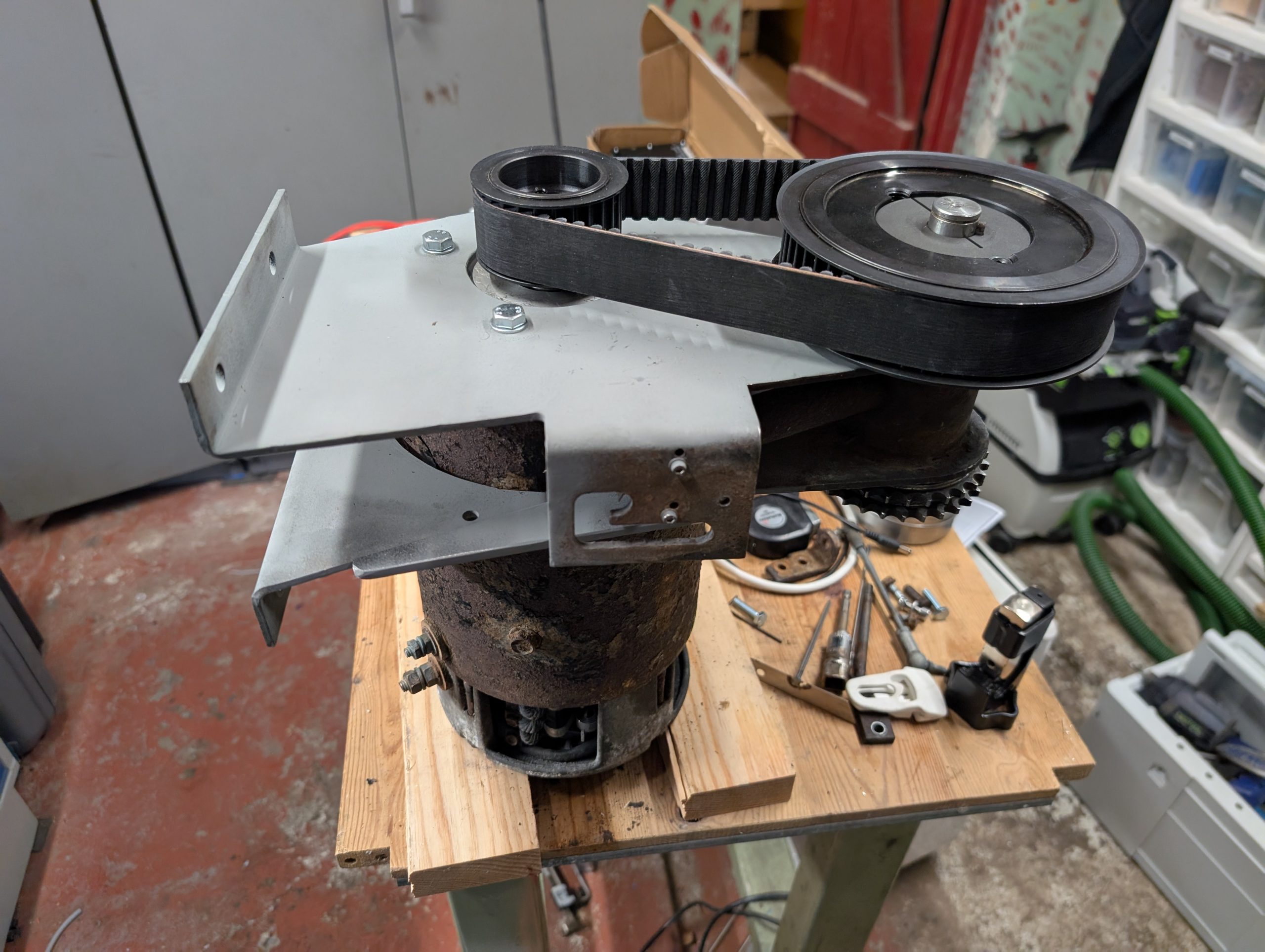
The big deal was the reduction gear using a timing belt and pulleys. The original motor used a 720×20 mm 8M HTD belt with 24 to 64 tooth pulleys (2.67 reduction). That resulted in a calculated center to center distance of 176.6 mm. Now things became an optimization problem. The new motor has a max speed of 2500 rpm. Calculating backwards on wheel circumference, chain reduction and desired speed (around 50 km/h) resulted in a calculated reduction of 2.2.
Pulleys and belt lengths only come in fixed variations. I needed a reduction of 2.2 with a center distance of about 176 mm. Creating a spreadsheet with available combinations resulted in a 26 and 56 tooth pulleys with a 688 mm belt. This gives a center distance of 175.8 mm. That is good enough.
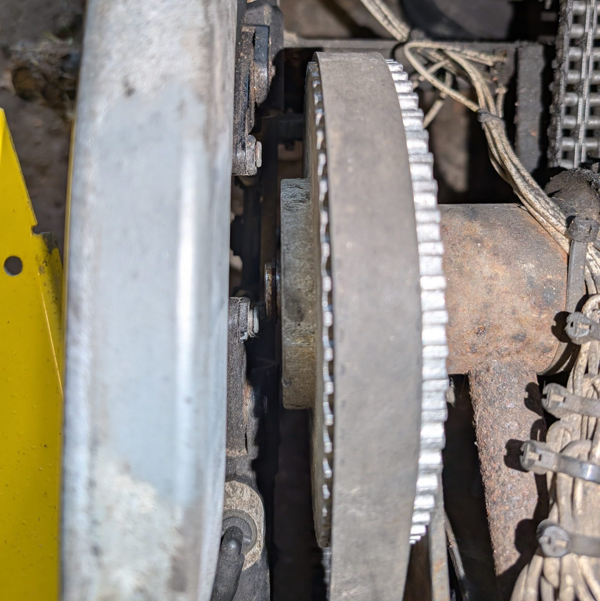
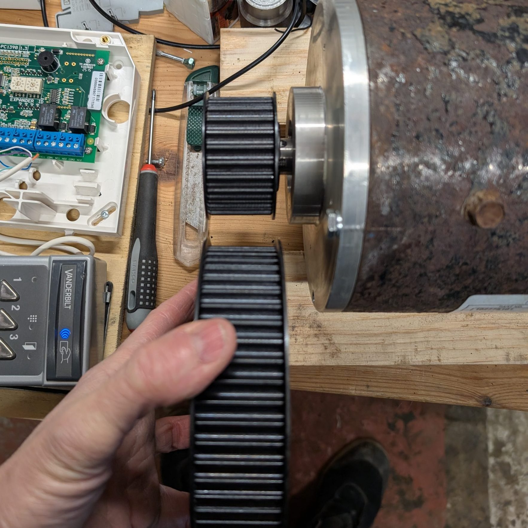
The potential torque of the new motor got me in doubt about using a 20 mm wide belt. Thorough measurements told me a 30 mm wide belt would fit. When I got the ordered pulleys and the belt it looked massive. It might have been enough with 20 mm but I hadn’t done any calculations at this point.
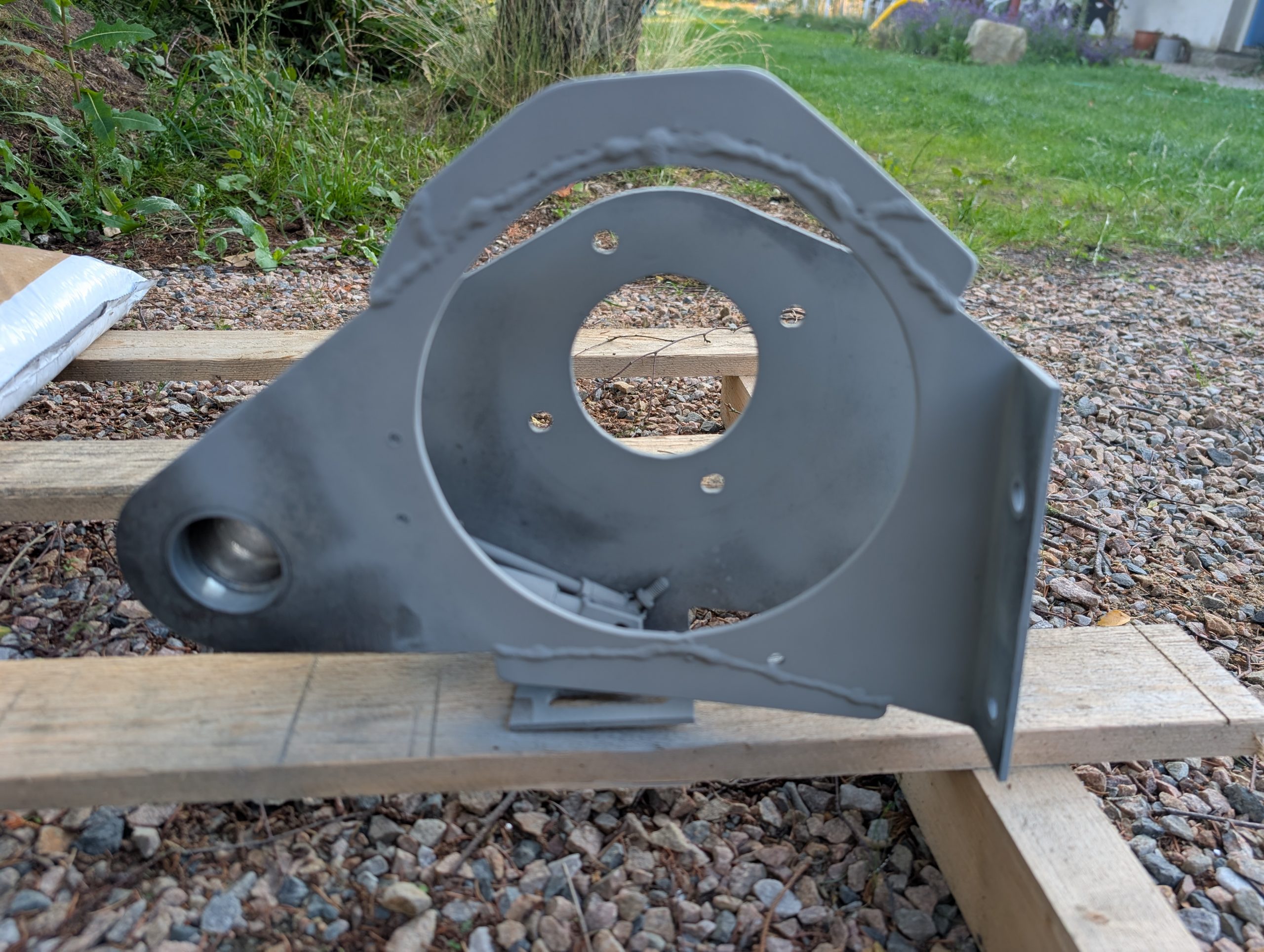
Now it was time to do the physical motor swap. The motor and belt reduction are all mounted on a separate bracket that can be removed. Quite convenient. I removed this, added some strengthening and cut open mounting holes for the new motor. Unfortunately I had to remove the parking brake because the linkage got in the way for the new motor. A problem that needs to be solved at a later point. The ball bearings for the shaft between the belt pulley and the chain were replaced.
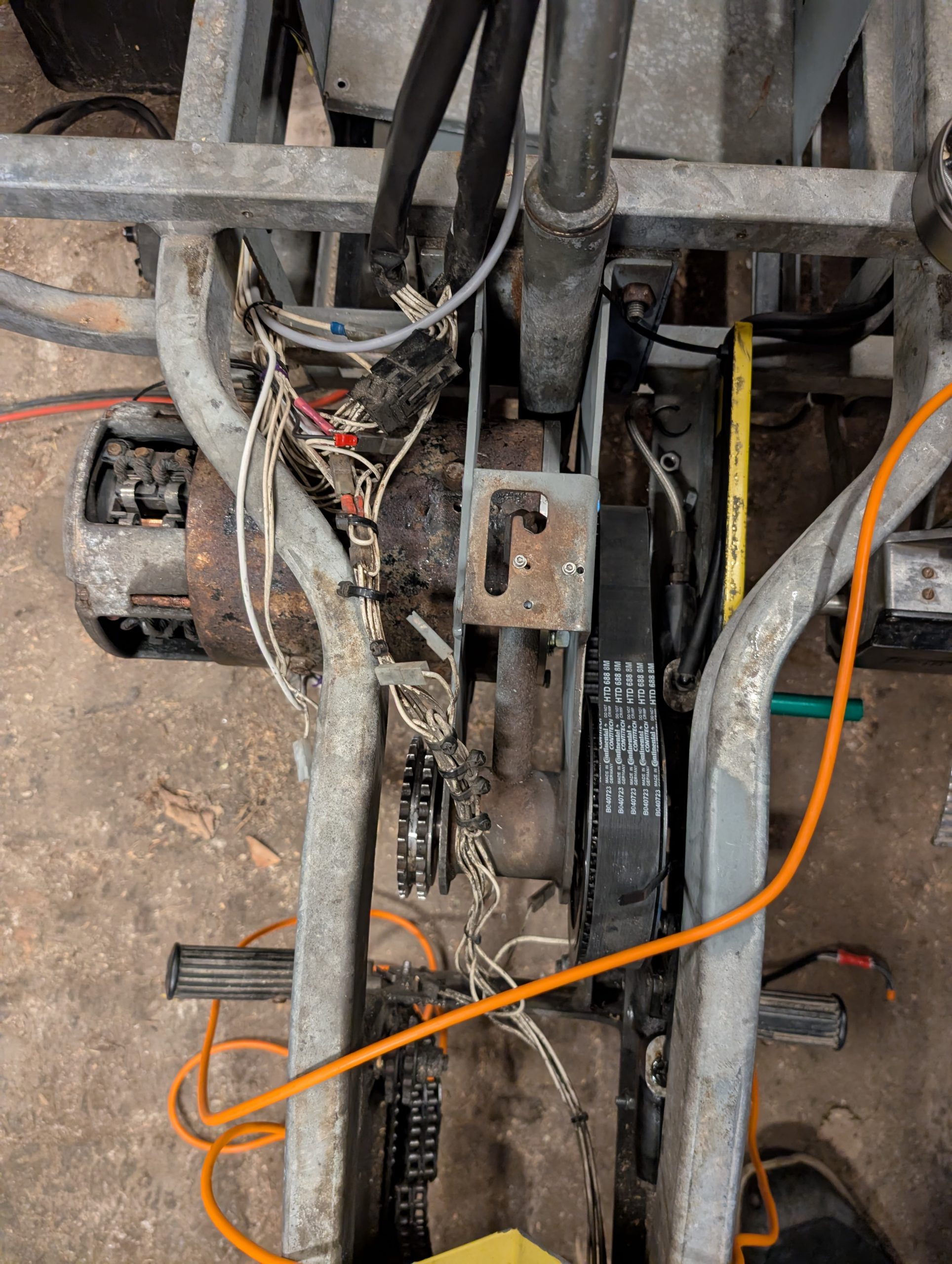
It was a pain to mount the bracket with the new motor due to the weight. I had to use a hydraulic floor jack to get it aligned but in the end it worked out fine. I also had to move the brake cylinders a bit to the right. A tight squeeze but possible.
Now, electronics! The motor controller that came with the complete Club Car electronics harness was a Curtis 1520-5501. It is an OEM version of the Curtis 1268. The 1268 has some quite nice features such as dual operation modes with different speed and acceleration settings that I planned to use. Unfortunately, it turned out later that the OEM version wasn’t versatile.
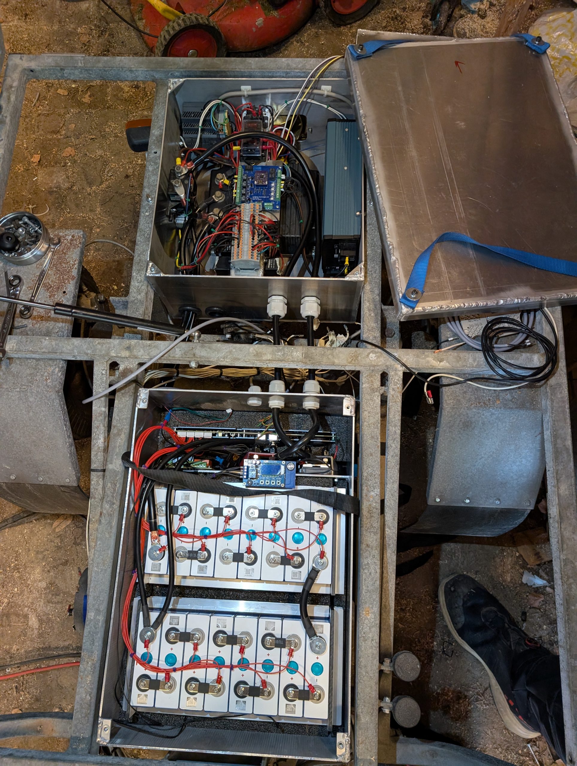
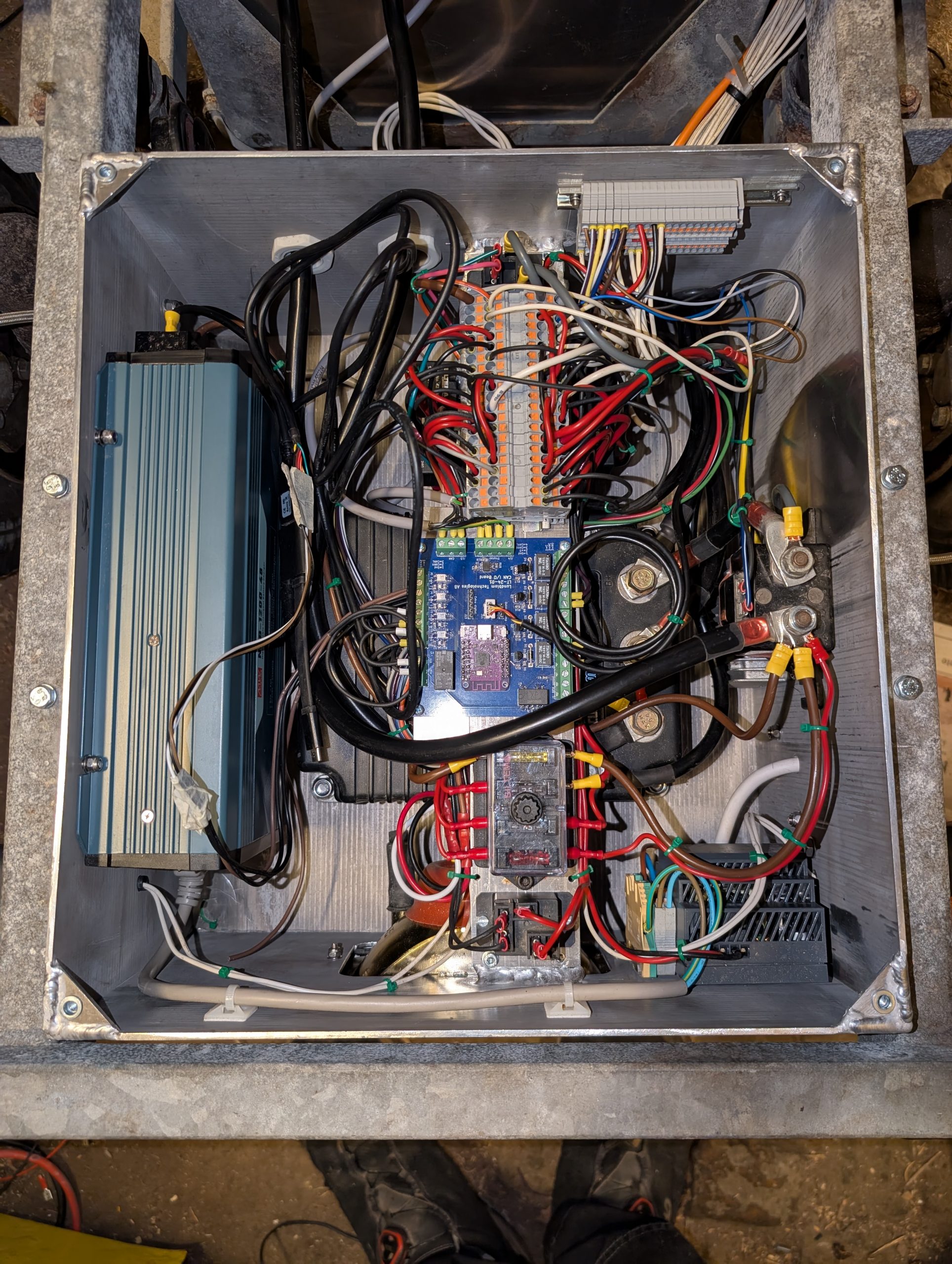
To get the motor running I would need the new controller with it’s auxiliary components such as high-current relay, speed sensor, etc. I also required the battery pack to be converted to 48 V and to get a new charger. The controller and the charger are the largest components and the existing electronics box started to look small. It was also pretty rusty.
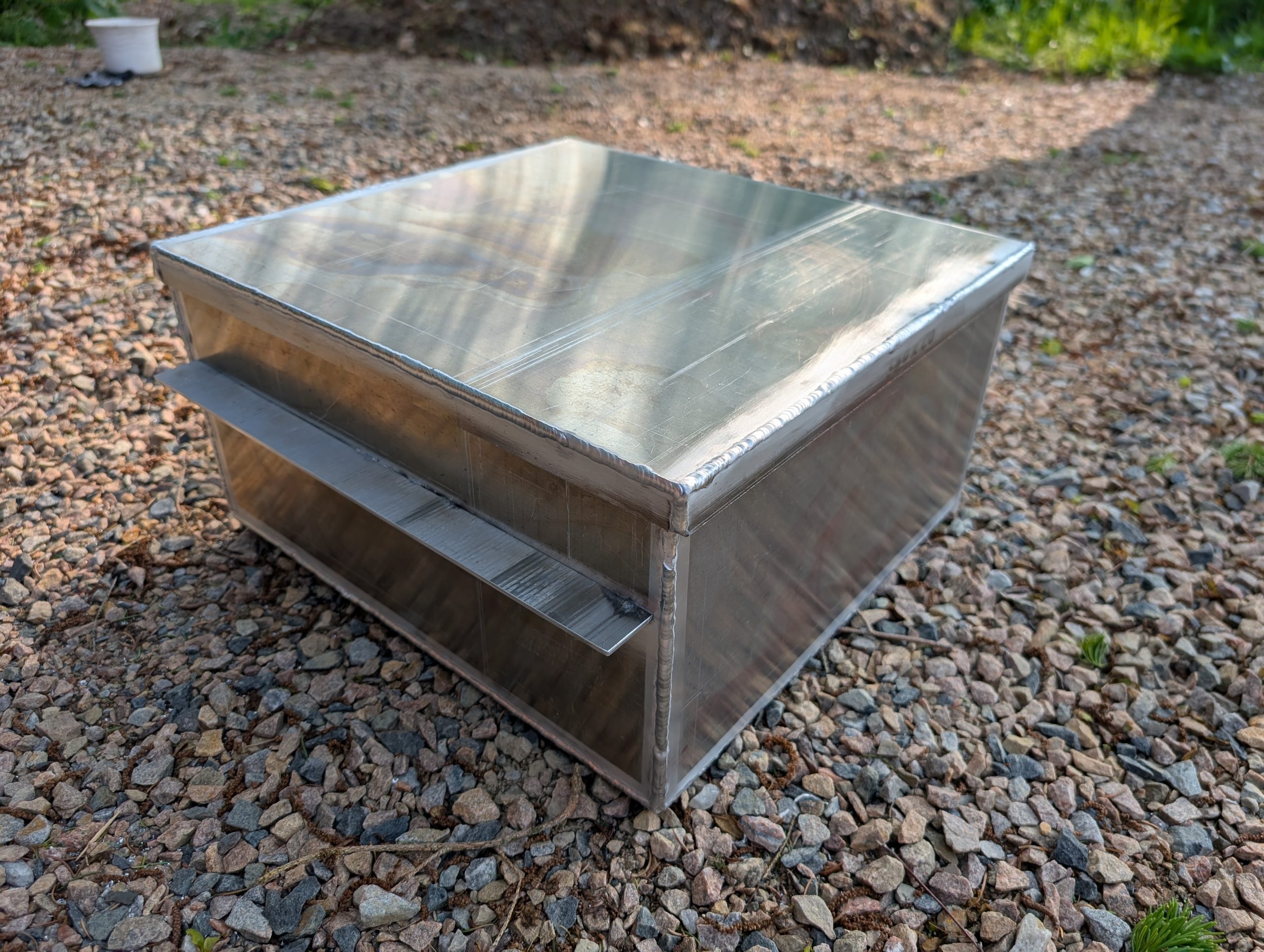
Before the actual motor swap was made, made the decision to weld a new larger box in aluminum to house the electronics. This was welded with my now-functional Chinese TIG welder. Turned out OK. The advantage of a new box was that I could start the design and wiring of everything on a desk rather than in the garage.
In the original setup, the head light of the moped is mounted in the electronics box. I think it looks better than the version where an external head light is used. For the new box I was considering a LED head light but wanted something proper. Not cheap stuff from Asia, but a good E-rated head light. Turned out these are not cheap (around €200) so that was out of the question. I did find out that one the nice Hella NovoLED headlight actually is a LED version of their 6213 H4 head light. This means, using a 6213 (cheap) an upgrade to a NovoLED can be done in the future without changing the hole pattern in the box.
I choose to build everything with part automotive relays, part DIN-rail automation products. A few parts from the original electronics were reused. As always, things grow more complicated with time. I aimed for clean wiring and ended up with the usual rats nest :(
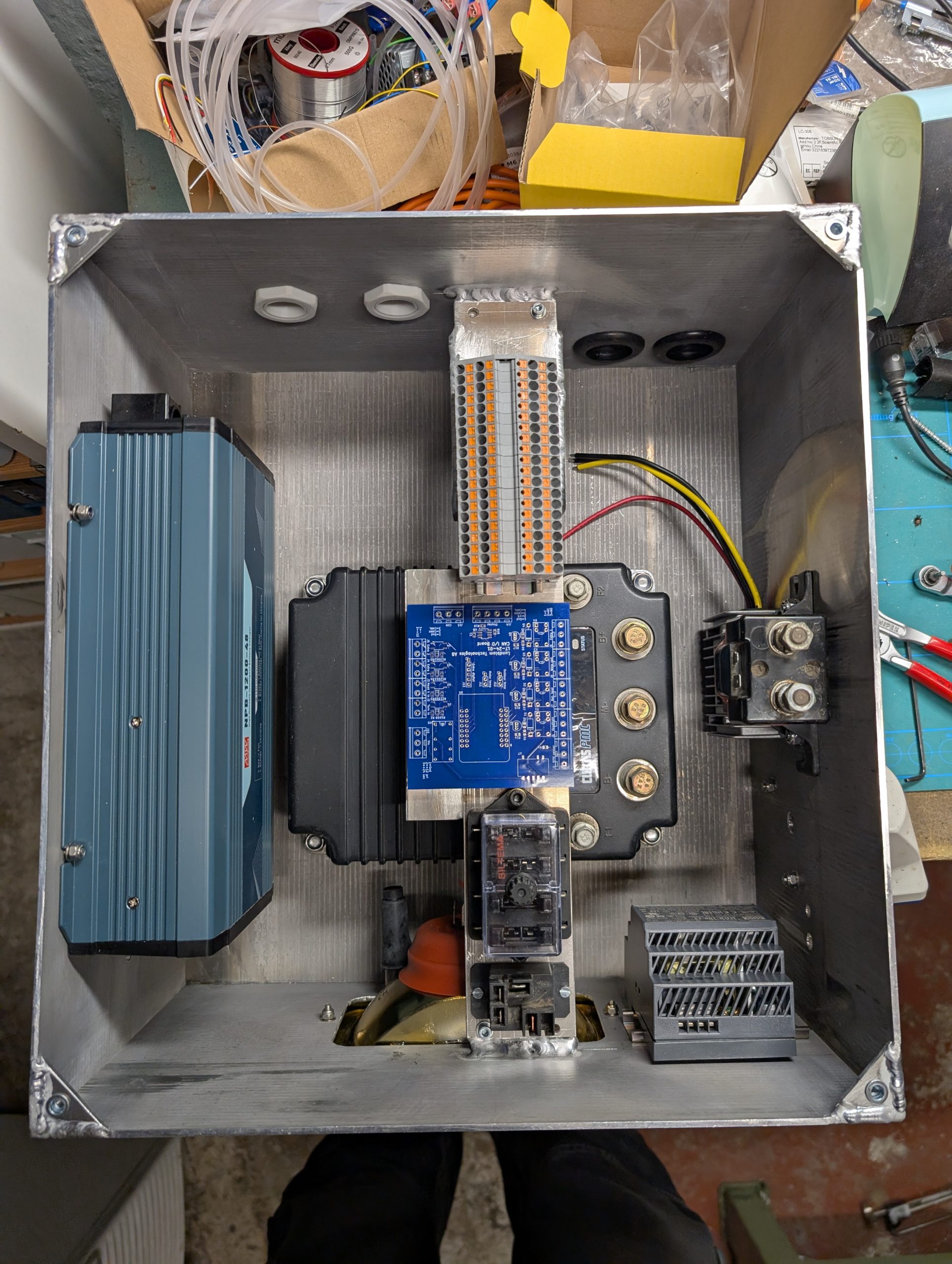
Again I had to crimp quite a few heavy-gauge cables. The routing of these affected where things were mounted in the box.
The battery was re-routed for 48 V operation with new balance cables. I also tried the new charger, a Mean Well NPB-1200, which was a compromise between price and performance. I have great experience with Mean Well products but would have preferred something more durable. Of course, the Mean Well charger needed configuration using a CAN bus cable. The official cable is expensive so I used a generic CAN interface and some lines of Python to get it done.
With the batteries at 48 V, the motor mounted and the most basic things connected it was time for a test run. Wow!
The motor ran great and with the new bearings on the belt-chain shaft the drive suddenly was silent. One thing became apparent though. The acceleration and/or max current draw needs to be limited in the Curtis controller to protect the batteries. The cells are rated for 1 C (105 A) continuously and it is easy to create peaks of 200 A (and probably more).
The good thing is that such parameters can be tweaked in software. This usually requires a proprietary Curtis interface and software. Luckily I found some USB converters at home that could be configured for this, and the software is floating on the interblag.
Digging deeper into the motor controller configuration software I realized that my OEM motor controller was lacking quite a few of the interesting configuration parameters available in the 1268 model. No dual operation modes, no way to disable some unnecessary golf-cart-specific functions etc. Well, that is what you get when you buy things cheap. At least I managed to set things like decent acceleration, limit the current peaks and regeneration voltage, and set an OK top speed.
At this point everything important was tested OK. It was now just a tedious job of reconnecting the existing wiring for lights and things.