
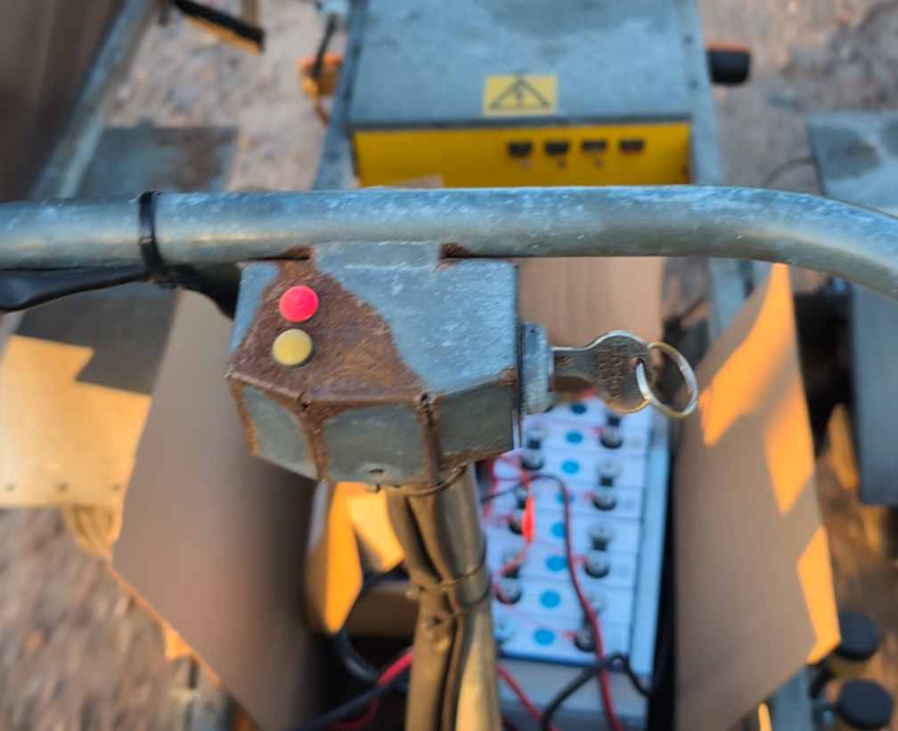
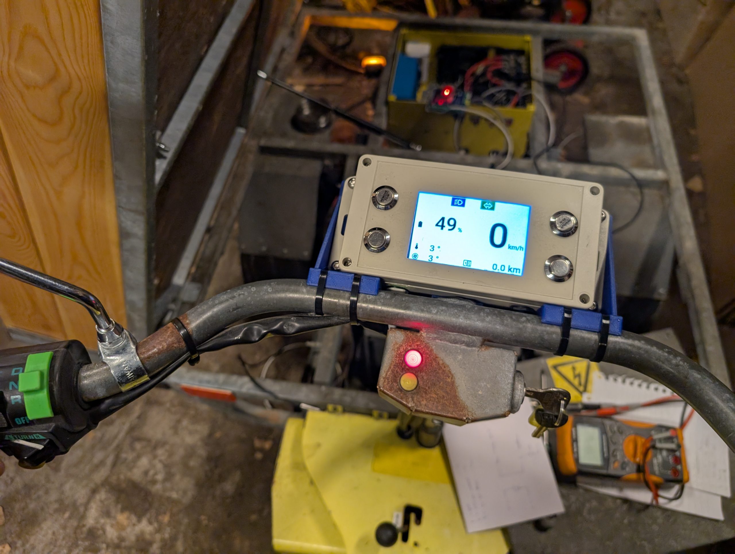
On my moped there are only two dash lights (ignition on, turn signal on). Also with the original lead-acid accumulators, there were no battery meter.
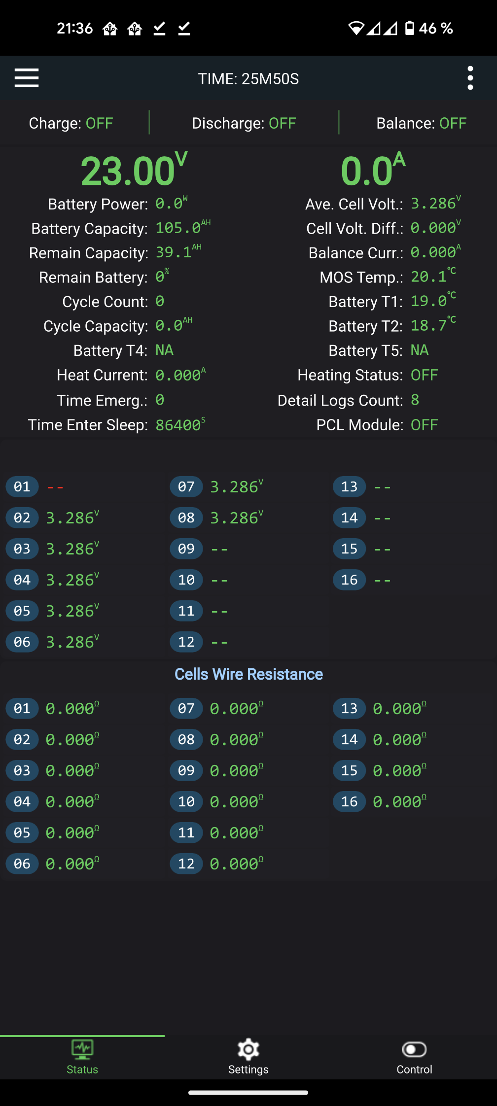
Not knowing the state of charge (SOC) of the battery is a bummer. Every time one want to know it, the crappy JK-BMS mobile app needs to be started and eventually connected to the BMS. Not ideal.
I also found a speedometer would be nice. Time to bring back some of my dusty electronics skills!
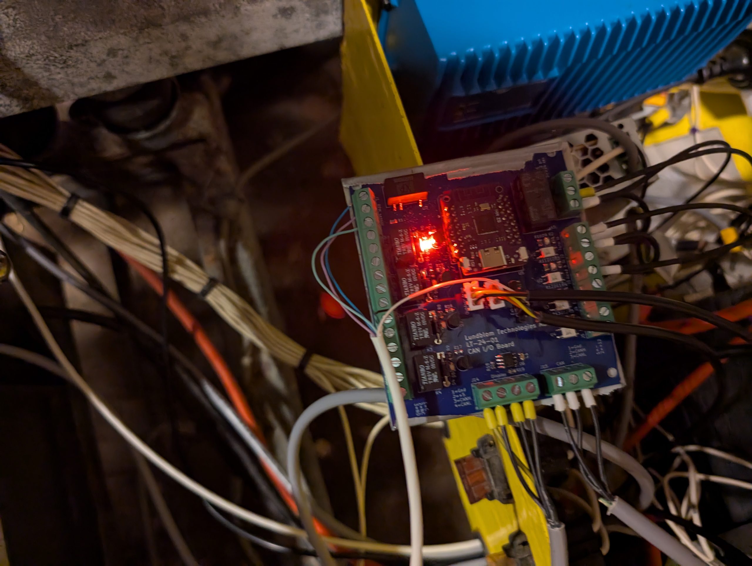
This was a perfect time to play with stuff I haven’t touched before. The BMS has both RS-458 and CAN interface, but I haven’t played with the latter. I wanted a graphical display on the handle bar so another opportunity to play with more advanced displays. In addition to this I wanted some input and output signals in the main electronics box (turn signal indicator, adding high/low beam headlight, etc.). Out of this grew a setup with two microcontrollers and the BMS on a CAN bus.
I have quite some experience coding for 8-bit AVRs and various ARM Cortex controllers but wanted something modern and quick to setup. The various ESP32 modules are cheap and I have used them with Home Assistant previously. The idea was to use the Arduino framework on these modules to get a quick start. (In the end Arduino wasn’t my thing though, more below.)
For the handlebar-mounted dashboard I wanted a large and bright color display. I only used smaller displays in the past so I just picked something reasonable large and cheap (3.5″ Raspberry Pi supported 480×320 SPI display). Should probably have done more research because this caused some pain.
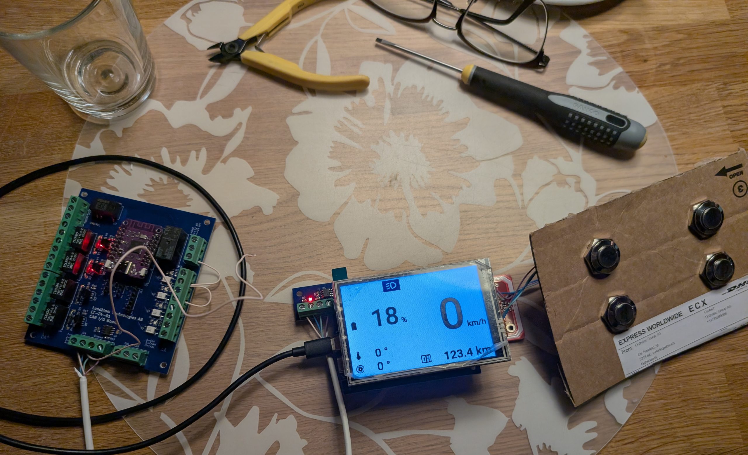
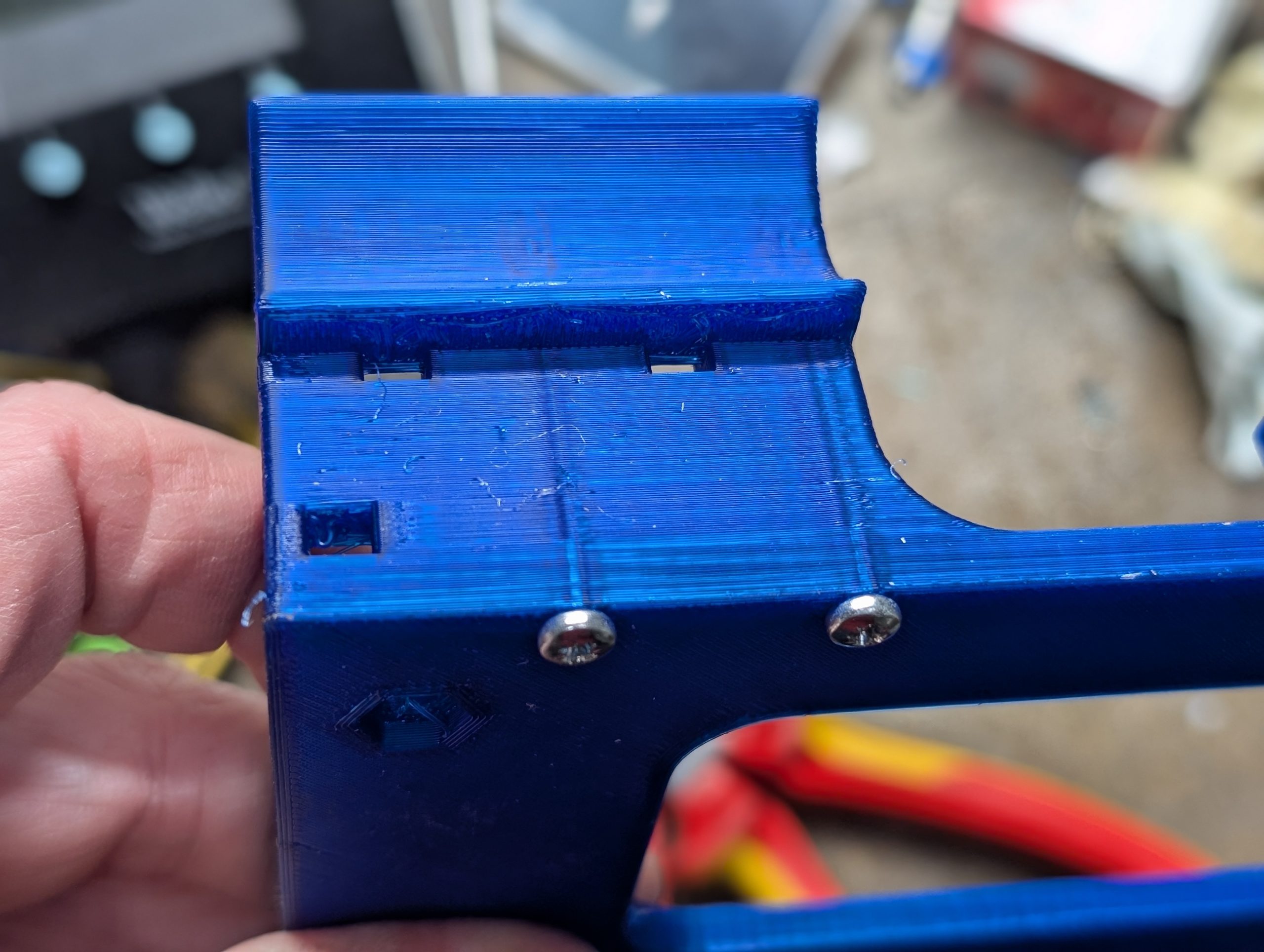
To this I added some buttons to be able to navigate menus on the dashboard. Idea was to 3D print some kind of enclosure housing the display, buttons and the dashboard ESP32 module. After quite some considerations I ended up using an ugly Hammond enclosure with a custom clear overlay for the display.
Both the dashboard ESP32 module and the I/O module that should go into the electronics box needed peripheral electronics such as power supply, galvanic separated I/Os and CAN tranceivers. There was a day when the best option for this would have been breadboard or a homemade PCB. Nowadays there are PCBWay and a simple two-layer PCB costs $10. So, I revved up my old KiCad skills and did some schematics and layout. Turned out quite OK.
Meanwhile I also started working on the software. I identified the hardest part to be the display. Both interfacing it and creating a usable UI. The display uses a controller called ILI9488 which has some drawbacks. The main thing is that it uses twice the number of data bytes for simple color handling over the SPI interface. This reduces the refresh rate to half. It also turned out that none of the initial libraries I tried did work. Finally I got a breakthrough with the TFT_eSPI library which implemented the correct 16-bit handling for the ILI9488.
Good but not great. The TFT_eSPI library supports basic display operations such as drawing lines, rectangles, fills, etc. I started to implement my own graphical menus using these primitives but it quickly got cumbersome (and the library code is quite ugly). Then my eyes turned to LVGL… Only one problem, no direct support for ILI9488.
In the end I found an almost working driver for ILI9488 and LVGL. It needed some adaptations to handle the said 16-bit interface but I got it running. Quite nice. I would say that the LVGL possibilities far outshines my graphical capabilities. Thus, the quite crappy-looking interface :)
With the display working, it became obvious that the hardware wasn’t that good. The view angle is bad, the brightness is bad (especially with the transparent overlay I used on the enclosure), the SPI interface is slow. It will suffice for now but there will be a Next Generation.
LVGL, some Inkscape sketches and quite some coding resulted in a decent dashboard layout with menu pages for non-essential controls and information such as battery information. Essential display data (speed and current draw) is updated twice every second, other data not that often.
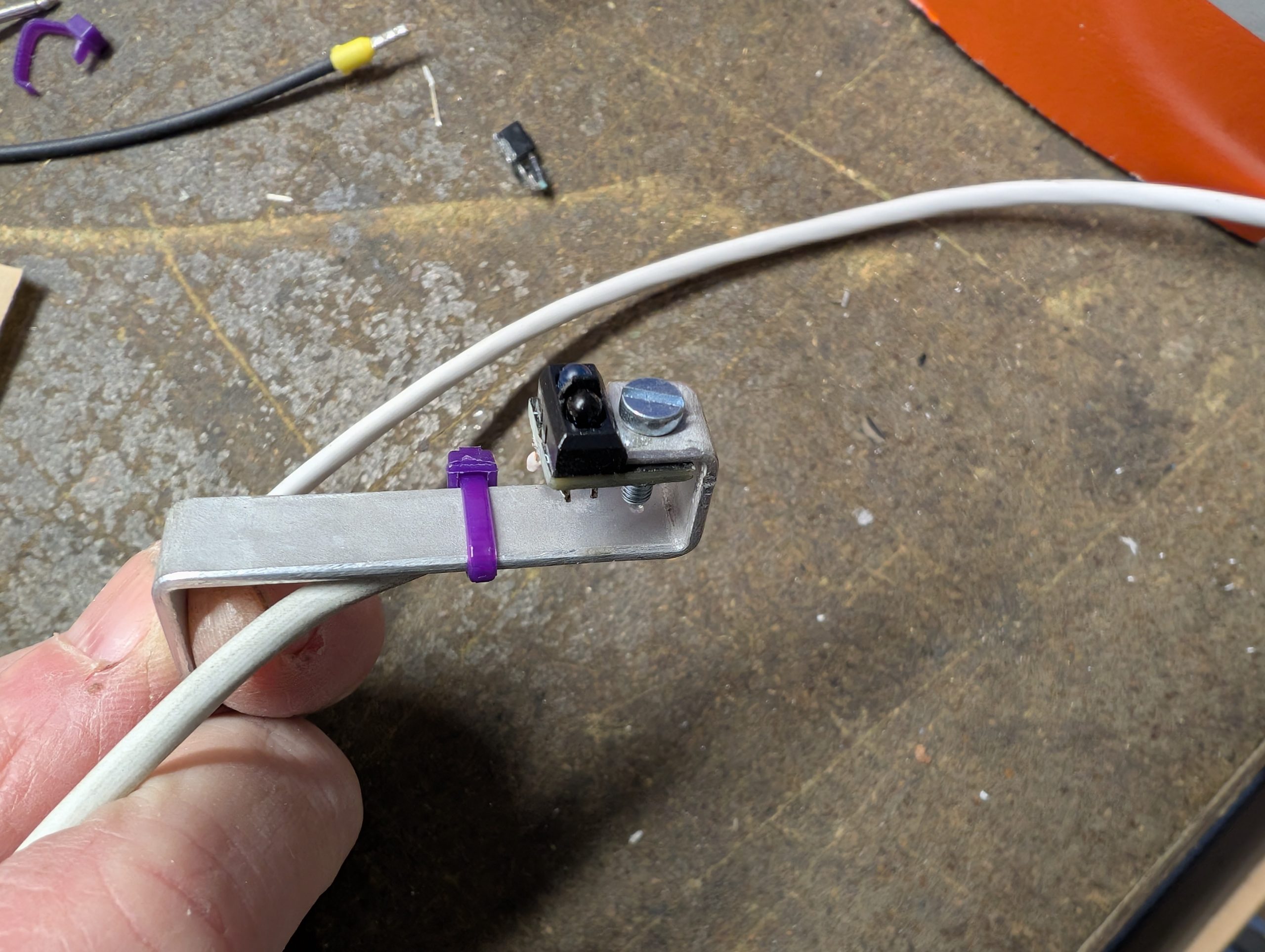
The other ESP32 based I/O module is pretty straightforward. Some inputs with optocouplers to easy handle different voltages, and some relay outputs. I also added connectors for two 1-wire temperature sensors to be able to read outdoor and motor temperature (the motor meltdowns, remember?). To get the current speed, I used an optic sensor reading some reflective tape on the motor pulley. This works because there is no freewheeling on the drive train. The same sensor is used to measure distance for a trip meter.
The IO module, the dashboard module and the BMS is all connected to the same CAN bus running at 250 kbit/s. The BMS periodically emits battery status messages which are picked up by the dashboard module. The IO and dashboard modules exchange data in a similar manner.
Because I ended up with a standard enclosure for the dashboard, I had to somehow mount it. My 3D printer and some zip ties to the rescue.
As of now, none of the ESP32 modules are running when the ignition is turned off. This is true also when the charger is active. The next version will probably have some kind of periodic wake-up and charging status indications. Because the ESP32’s are so easy to connect to WLAN (WiFi for the younger ones), one possibility is to let it report status to Home Assistant when parked at home.
In the initial sections, I mentioned Arduino. I never liked it for the AVRs (used my own bare metal libraries) and I definitely don’t like it on the ESP’s. It is way to simple, most libraries are lacking features, are not being consistent and so on. After some digging I realized it was all running on the ESP-IDF framework, which in turn is running on FreeRTOS (Hi, friend!). So I rewrote all dashboard code to ESP-IDF utilizing the IDF libraries for peripherals and FreeRTOS primitives for tasks and similar. I really like that combination!
I even got OTA over WLAN to play nice in this setup. Now I can trigger an update by pressing some buttons when turning on the ignition. So much easier than accessing the module with a USB cable.
This is all for this post. During the project I have gotten ideas enough to motivate an upgrade of both the dashboard (using a better display) and the I/O card. My idea is to run everything through the I/O card instead of having separate relays for high/low headlight, turn signal and so on. Maybe something for the winter.